
Redundant Firewalls with PF and CARP
Part 1 of 2: Requirements and Hardware
Eric M. Johnston
23 June 2007, Initial revision.
- Overview
- Basic Network Configuration
- Hardware Requirements
- Hardware Selection
- Motherboard Assembly
- Serial Console Cable
- BIOS Configuration
- Final Assembly
Overview
Last month I needed to provide firewall protection for a small startup's rack of servers (placed in a collocation facility) connected to the Internet via an Ethernet connection. The ISP allocated us a /29 network (essentially, 5 IP addresses), so the firewall has to perform Network Address Translation (NAT) on the internal networks and expose services to the outside world as appropriate on our set of external addresses. Since there's only a single upstream Internet provider, we don't need fancy stuff like BGP.However, the company had just signed a service level agreement with an important customer and suddenly reliability became an important part of the requirements. This being a startup, I had to carefully consider every dollar spent, pretty much eliminating expensive Cisco (or similar) gear. I use OpenBSD's Packet Filter (PF) on my own network at home, and had heard nothing but good things about the Common Address Redundancy Protocol (CARP) for providing firewall failover: they seemed to be the perfect fit.
While I generally prefer FreeBSD as a server operating system and the latest releases include both PF and CARP, I decided to go to the source for these dedicated firewalls: OpenBSD. OpenBSD can't be beat for its focus on both networking and security and, since PF and CARP are developed and maintained on OpenBSD, I knew I wouldn't run into any annoying incompatibilities or interoperability problems.
This two part article is intended to be a complete guide to building a
redundant pair of dedicated, diskless OpenBSD firewalls, covering requirements
and hardware selection & assembly (part 1) and ruleset configuration
(part 2, coming soon).
There's a ton of excellent PF and CARP documentation out there, but I spent a
great deal of time piecing it all together for my particular application.
Additionally, unless you're already familiar with how PF and CARP work
together, sometimes it can be hard to get things cooperating without a lot of
trial and error. Hopefully this primer will help make the whole process a
little easier to understand.
Basic Network Configuration
Before jumping into the hardware, we need to first understand the overall
architecture strategy to define the network interfaces. Figure 1 below gives
a very basic overview of the configuration. I've segmented the network into a
couple of different subnets in order to separate traffic. This is useful for
a couple of reasons: first, it allows us to easily define different firewall
rules for each subnet depending on function; second, we can isolate and
address performance issues on one subnet without affecting the others.
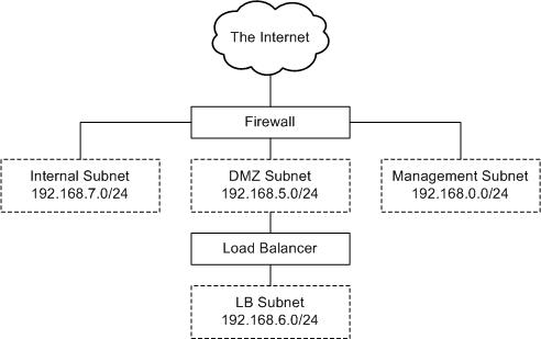 |
Figure 1: Network architecture. |
|---|
For example, the DMZ Subnet is where requests from the outside world are sent. The Internal Subnet is where database traffic, NFS shares, etc. live. Consequently, the DMZ Subnet has far less restrictive firewall rules than the Internal Subnet and we can also restrict traffic between the two. While both subnets are connected to the same switch as separate VLANs, as traffic grows we can easily add a switch dedicated to, e.g., the Internal Subnet.
As shown in the diagram, the firewall has to make 4 network connections: one upstream to the Internet and one each to the Internal, DMZ, and Management subnets. However, in order to support failover between a redundant pair of firewalls, we'll need an additional interface for synchronizing PF's state table. Therefore, our five interfaces are:
- Upstream Internet connection.
- DMZ Subnet: production services reachable from the outside world.
- Internal Subnet: production traffic among servers internally.
- Management Subnet: utility network for managing devices; doesn't carry production traffic.
- PF Synchronization.
Hardware Requirements
Now that we know basically what our firewalls have to do, we can start to spec out the hardware. Here are the core hardware requirements I identified for this project:- OpenBSD must natively support all hardware.
- At least 5 network interfaces, all 100 Mbps or faster.
- A well supported and inexpensive architecture: i386, non-SMP. I wanted to be conservative in my architecture choice to ensure the most reliable configuration possible. While multiple processors or cores and 64-bit architectures are certainly attractive and affordable these days, they're still relatively new and I didn't see this project as the place to try out new things. Furthermore, a single processor i386 machine should be more than capable of handling the traffic we're expecting for the time being.
- 1U chassis height. Rack space is a precious commodity, and we can't afford to have two firewalls take up a big chunk of the available space.
- Diskless configuration. Disk drives have moving parts, and moving parts like to fail. Also, the firewalls don't really need that much storage to begin with, and even the smallest hard drives available today are way bigger than what's necessary for this application. Mirroring (RAID 1) is really the only way to have disk storage in this sort of situation, but it complicates things, makes the chassis bigger, uses more power, and increases costs.
- Headless operation. Ideally, all machine configuration and operation should be possible over a serial console connection. (Sometimes getting the right cables and settings for serial communications can be a royal pain but well worth the effort -- a console connection allows you to eliminate so many variables when troubleshooting.)
- Redundant power supplies. Since I've got two firewalls anyway, this feature really isn't necessary.
- CD-ROM/floppy drives. For both simplicity and security, I didn't feel that the firewalls should have removable media.
Hardware Selection
Taking into account the above requirements and a tight budget, I settled on the following shopping list for each firewall. They're identically configured, so both should behave exactly the same. This list should not be treated as definitive: the prices I've listed (USD) are undoubtedly already inaccurate and the equipment, if not yet out-of-date, soon will be. Thus, consider this as merely starting point for your research.
| Vendor | Part | Description | Price |
|---|---|---|---|
| General Technics | J1631 | IPC Modular 1U ATX (Black) Chassis | 163.00 |
| General Technics | PS585 | 250 Watt Power Supply, 1U | 85.00 |
| General Technics | RK411 | 6 RJ45 LAN+1 RJ45 Serial Module | 49.00 |
| General Technics | RK413 | Rear Panel, Vented | 12.00 |
| General Technics | HW138 | P4 775 Passive Cooler Low Profile | 30.00 |
| General Technics | RK570 | 64-bit PCI Riser Card, 1U ATX | 15.00 |
| Intel | SE7230NH1LX | ATX Motherboard | 253.32 |
| Intel | BX80547RE2800CN | Celeron D 336 2.8 GHz LGA775 | 37.00 |
| Syba | SD-CF-IDE-A | IDE to Compact Flash Adapter | 10.99 |
| SanDisk | SDCFB-256-A10 | 256 MB Compact Flash Card | 5.88 |
| Soekris | lan1641 | PCI Quad Ethernet Board | 95.00 |
| Kingston | KVR533D2E4/1GI | 1GB 240-Pin DDR2 SDRAM ECC | 48.99 |
| - | - | DB9 Female to RJ45 Modular Adapter | 1.14 |
| Total hardware cost per firewall (before shipping, taxes, etc.): | $806.32 | ||
A few notes about these choices: For the chassis, after an exhaustive search, I finally settled on a solution General Technics offers with their line of 1U modular rackmount cases. The chassis is short depth, saving some space, and the front 5.25" bay can accommodate a couple of different modules. The most interesting option for this project is the front-mounted LAN and console connection panel. With this configuration, the case rear is just a vent; only power is connected on the back. To ensure that everything fits, I stayed with General Technics for the power supply (only 250 watts for our modest processor and no drives), the processor heat sink, and the PCI riser card. (Even though the Ethernet card I chose is 32-bit, I got a 64-bit riser in case I ever need to upgrade the card.)
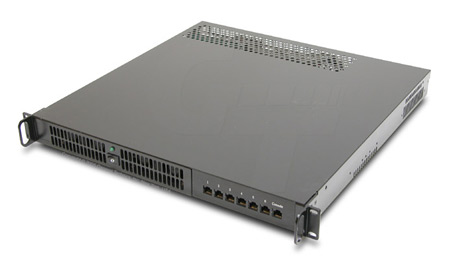
Figure 2: General Technics' 1U chassis with front LAN & serial connections.
I chose the Intel SE7230NH1LX based largely on the literature on General Technics' website. It's a nicely equipped server-class motherboard, has got two onboard Intel gigabit Ethernet interfaces, and supports console redirection to serial. However, as I note later, it's not a perfect fit for the chassis.
For the processor, simply put, I went with the cheapest CPU that would fit the motherboard. A 2.8 GHz Celeron D should be plenty of horsepower for these firewalls. Two things to consider, though: first, under high traffic (packet) loads, the ability of the processor to handle the interrupts becomes a concern. I'll have to keep an eye on how this Celeron performs with my Ethernet card choice. Second, power is a pretty big expense in a collocation facility and some of the newer, less energy hungry processors could be a better choice for a full rack.
I've read some mixed reviews about the Soekris lan1641 quad port Ethernet cards. It looked like some folks have had trouble with them under FreeBSD or OpenBSD but, reviewing the sis(4) commit logs, it looks like most of those problems have been resolved. Though I would much prefer to use the Intel quad port cards, at about 1/5th the price, the Soekris should be fine, especially for the interfaces that aren't going to be seeing production traffic. (I can always upgrade later, if necessary.)
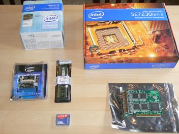
Figure 3: CPU, motherboard, quad Ethernet adapter , Compact Flash card, RAM, and IDE-to-CF adapter.
RAM is cheap, and I saw no need to skimp; ECC memory is standard in such an application. 1 GB should be plenty for a machine that isn't running much more than PF and sshd. Keep in mind, though, that these machines won't have swap (no disks!) and we'll be mounting the file systems as RAM disks.
The IDE-to-Compact Flash adapter and CF card combination is the one spot where
I experienced some trouble. I had originally purchased some 1 GB Transcend Compact Flash cards for
this project. However, these newer cards (part number TS1GCF80) are capable
of DMA mode, which the IDE adapter evidently doesn't support. This only
confused both the motherboard and OpenBSD, causing reads to be very slow
(i.e., hours to load the kernel on boot). The Intel motherboard's BIOS
doesn't seem to allow you to disable DMA for a drive, and disabling DMA for
the device in the OpenBSD kernel doesn't help the booting situation. It was
clear I wasn't going to use anywhere near 1 GB on the card so, after
downgrading to the 256 MB SanDisk cards,
everything worked fine. (Transcend also appears to offer a
PIO mode
version, part number TS1GCF80-P, that might work, though I haven't
tested it.)
Motherboard Assembly
So, assembling the firewalls requires a bit of experience with computer
hardware. If you haven't installed a CPU or crimped CAT5 connectors, this
project might be a little too much. As for tools, you'll need a standard
compliment of screwdrivers and pliers. The only somewhat special tools
necessary are a soldering iron for the serial console adapter and a crimping
tool to make a crossover patch cable (if you don't have one handy) for part 2
of the article.
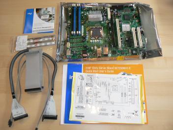
First, unpack the motherboard. It comes with a couple of drive cables, a standard ATX back plate (which we won't need), and some documentation and CDs (figure 4). The included quick start guide has pretty clear directions for installing the CPU.
 |
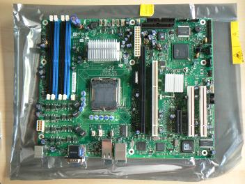 |
| Figure 4: Motherboard contents. | Figure 5: Top view of motherboard. |
|---|
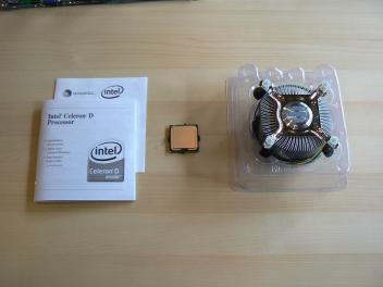
Next, unpack the CPU (figure 6). It comes with a large heat sink and fan, which we won't be using -- there's no way it'll fit in our 1U case. Double check that the CPU's installation instructions jibe with the motherboard's. Since both the motherboard and processor are Intel in this example, the docs are nearly identical. Really, there's only one way to put in the CPU given the keying, but you want to make sure you remove all of the appropriate plastic parts and operate the levers correctly so you don't break anything.
 |
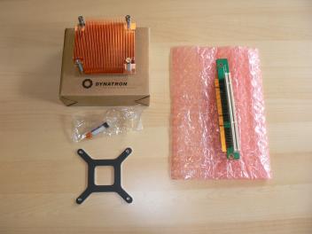 |
| Figure 6: Celeron contents. | Figure 7: CPU heat sink and PCI riser card. |
|---|
Figure 7 shows the contents of the passive heat sink we ordered with the chassis (the one General Technics sent is made by Dynatron, model P13G). The hefty copper heat sink comes with some thermal paste and a brace which fits on the rear of the motherboard. Also shown in figure 7 is the PCI riser card; set it aside for now.
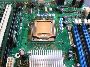
Go ahead and install the CPU according to the instructions. Once it's in (figure 8), line up the heat sink's brace on the motherboard bottom with the four mounting holes surrounding the CPU (figure 9).
 |
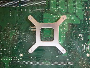 |
| Figure 8: Processor installed. | Figure 9: Heat sink brace on motherboard bottom. |
|---|
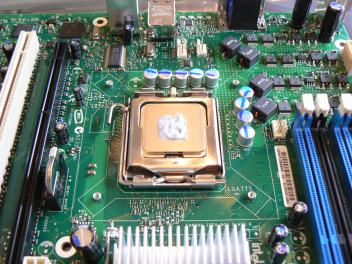
Next, clean the top of the CPU and the bottom of the heat sink with a cotton swab and some alcohol. We don't want anything to compromise heat transfer between the processor and cooler. Apply some thermal paste to the center of the CPU, but don't overdo it (figure 10). Carefully mount the heat sink, making sure that the fins run from front to back so that air can flow (figure 11). Note that there are a number of different types of processors and that the best way to mount a cooler varies. Consult the CPU's instructions and the Web for advice.
 |
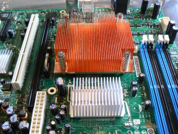 |
| Figure 10: CPU with some thermal paste. | Figure 11: Heat sink installed, fins running front to back. |
|---|
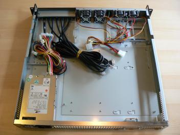
So, now the motherboard is pretty much ready for the chassis (figure 12). We can't really mount it in the chassis just yet, though: the monitor and keyboard connections we'll need to configure things for the first time won't really fit in when the motherboard is screwed down. Besides, I like to test things out before fastening everything.
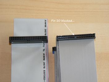
A word of warning: there's a good possibility that the IDE cable supplied with your motherboard won't quite work with the IDE-to-CF adapter. Ordinarily, pin 20 on IDE cables is used as a key to ensure that the cable is installed properly. Drives are usually missing pin 20, and cables have pin 20 blocked (figure 13). However, the IDE-to-CF people decided that pin 20 would be handy for powering the adapter. That trick may be convenient in some scenarios, but here it can be pretty annoying. I happened to have some older IDE cables lying around without pin 20 blocked; if you don't, you'll have to either carefully remove the pin from the adapter or drill out the cable.
 |
 |
| Figure 12: Inside the chassis, as shipped. | Figure 13: IDE cables. The one on the right has pin 20 blocked. |
|---|
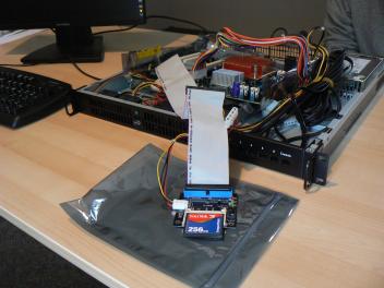
Let's "dry fit" the motherboard (figure 14). Line the chassis with the motherboard's anti-static bag and lay the board on top. Install the RAM on the motherboard. Go ahead and connect the power supply to the motherboard (don't worry if there seem to be some extra power pins on the motherboard's connectors; there should be only one way you can plug in the power). Connect up the chassis power switch and any LED indicators it's got. Plug in the IDE cable and floppy drive power to add the CF adapter, making sure that any jumpers the adapter might have are set appropriately for the power input. Insert a Compact Flash card into the adapter, even if it's not bootable yet, so the BIOS will see a drive. Hook up a keyboard and monitor; we'll skip installing the Ethernet card for now.
 |
| Figure 14: Motherboard connected, but not mounted. |
|---|
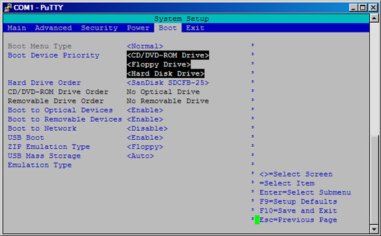
Now for our big test: plug in the power supply and turn on the computer. If all goes well, we should see a nice BIOS splash screen and it should recognize our Compact Flash "drive". This is an excellent opportunity to make sure the BIOS is up-to-date. Sometimes, an older BIOS might not recognize IDE flash card adapters and upgrading will fix things. To upgrade the firmware, you can hook up a floppy, CD-ROM, or hard drive to flash the BIOS, or you can check out my quick recipe for making a bootable DOS flash card. If the motherboard's BIOS is too old to recognize the IDE adapter, you might still be able to boot off of a USB flash card reader. Figure 15 is a BIOS screenshot showing our SanDisk card as a hard drive:
 |
| Figure 15: BIOS boot menu showing flash card. |
|---|
Serial Console Cable
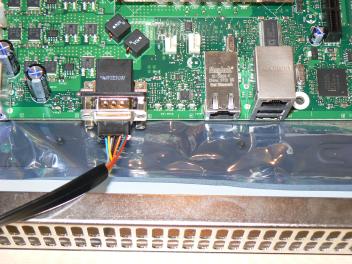
The General Technics chassis comes with a cable to connect the motherboard's
male DB9 serial port to the front-mounted RJ45 hookup (figure 16). However,
it doesn't do you much good unless you can convert it back to something usable
on your laptop, etc. Our solution is wire up a DB9-to-RJ45 modular adapter
(figure 17) with a regular old CAT5 patch cable connecting the adapter to the
chassis. Since we're connecting two computers, there's one twist: we need to
wire the adapter to make a
null modem connection.
 |
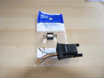 |
| Figure 16: Chassis console port connected to the motherboard. | Figure 17: Female DB9-to-RJ45 modular adapter. |
|---|
There are a number of sites with information on wiring a null modem cable; nullmodem.com seems to be fairly comprehensive. My experience has been that these modular adapters are pretty consistent in their color coding and RJ45 pinouts, but you'll definitely want to double-check that the pinout I give here is going to work with your setup. The following table lists the pinout on the chassis cable and the pinout you'll need for the adapter:
| Pin | Case's Cable | Adapter |
|---|---|---|
| 1 | - | - |
| 2 | Yellow | Black |
| 3 | Black | Yellow |
| 4 | Orange | Blue |
| 5 | Green & Red | Green & Red |
| 6 | Blue | Orange |
| 7 | Gray (or White) | Brown |
| 8 | Brown | Gray (or White) |
| 9 | - | - |
Ordinarily, putting together the adapter would be a simple matter of sliding the cable ends into the DB9 connector and snapping it all together. However, pin 5 presents a challenge: both the green and red wires need to be connected to this pin. Really, the only clean way to do this (at least with the adapter I got) is to solder the wires together. Just snip the end off of one of the wires, strip some insulation off the tip, and solder it to the other wire. If you want to get fancy, some heat shrink tubing will make things nice and clean.
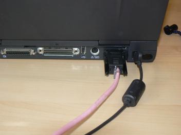
Once you're done, plug the adapter into another computer (figure 18) and connect to the firewall using a regular straight-through CAT5 patch cable (figure 19). We'll test it in the next section after the BIOS is properly setup.
 |
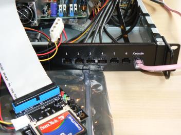 |
| Figure 18: Serial connection on a laptop using adapter. | Figure 19: CAT5 patch cable connected to chassis console port. |
|---|
BIOS Configuration
While you've still got the motherboard connected to a real keyboard and
monitor, there are a few BIOS configuration items that need to be taken care of.
Now, unless you've got the exact same motherboard I've got (an Intel
SE7230NH1LX), these instructions are not going to directly apply. However,
the options should be similar.
- Redirect console to the serial port. Note that some motherboards don't
have this capability, which means you won't have control of the server over
console until OpenBSD starts booting.
Advanced: Video Configuration: Console Redirection (Serial Port): <Enable>
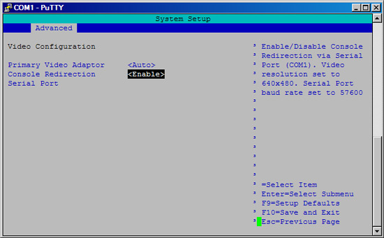
Figure 20: BIOS console redirect configuration. - Disable chassis intrusion warnings. This may just be an Intel motherboard
peculiarity; my chassis doesn't have an intrusion sensor, so I don't want this
option getting in my way.
Security: Chassis Intrusion: <Disable>
- Make sure the server will come back up after a power failure:
Power: After Power Failure: <Last State>
While the firewall is booting, on the console you should see a series of post codes and then an option to enter the BIOS (F2 for the Intel motherboard). Unfortunately, depending on how the serial console and motherboard interact, the F2 key may not translate properly for the BIOS to recognize it. I discovered (after much searching and button pressing) that the special incantation is Escape-2. I couldn't find this tidbit in any of the Intel documentation.
Once you're confident that you can access and configure the server from a
serial console, you can start mounting everything in the chassis.
Final Assembly
Now that the motherboard is working, the BIOS is updated and configured, and
we've got a working serial console, we're ready to ditch the keyboard and
monitor for good and start mounting everything to the chassis. The chassis
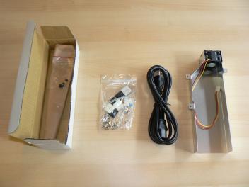
comes with a collection of screws, spacers, rubber feet, and zip tie mounts.
It's also got some brackets for supporting the rear of the chassis in your
rack (figure 21, left) and a CPU fan duct (figure 21, right).
 |
| Figure 21: Chassis accessories. |
|---|
Despite the notes on General Technics' website, the included fan duct does not fit with the Intel SE7230NH1LX, at least not using the heat sink I received. I can see how it might work with a different heat sink, or if I were to cut the duct up in a few strategic spots. However, given the chassis fan arrangement and the omission of hard drives in this configuration, the CPU seems to run cool enough without the duct.
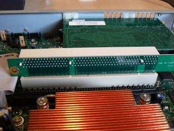
Another incompatibility between the SE7230NH1LX and this chassis is with the PCI slot placement. The slot is a little too far left for a normal height card to fit and mount with a riser on the supplied bracket. As you'll see, I had to improvise a bit to make things work. It's certainly a non-optimal arrangement, but not a showstopper.
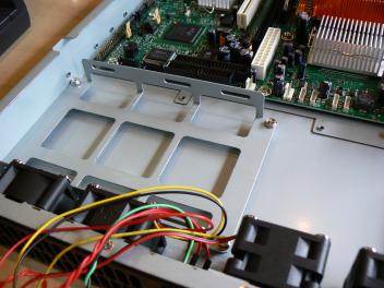
With power disconnected, go ahead and mount the motherboard to the chassis. Note that a few mount points require the use of the supplied spacers which latch into the chassis mounting plate. Remove the hard drive mounting bracket (figure 22).
 |
 |
| Figure 22: Hard drive mounting bracket. | Figure 23: Soekris Ethernet adapter, with bracket removed. |
|---|
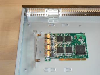
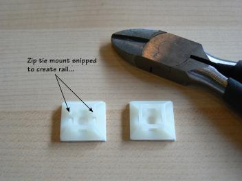
Now, carefully remove the mounting bracket from the Soekris quad port Ethernet adapter (figure 23). You'll also need to remove the PCI card bracket on the chassis, in the rear left corner. Mine was in there pretty tightly and required some persuasion. Next, create some card "rails" using two zip tie mounts. Just snip off two sides of a mount; the width is just about perfect for the PCI card (figure 24). Stick the mounts to the side of the chassis at the card's level when it's inserted into the riser, as in figure 25. Be sure to space them so that both sides of the card are supported.
 |
 |
| Figure 24: Zip tie mount converted to a PCI card rail. | Figure 25: Ethernet card installed with 'rails' and riser. |
|---|
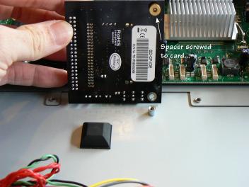
Finally, we can mount the IDE-to-CF adapter. The card's mounting holes are not very conveniently placed; they don't match up with any of the chassis' mount points. I settled on screwing in just one side of the card, attaching a spacer on the other side to level things out, and sticking a rubber foot on the chassis to support the card's rear (figure 26). This gives a reasonably snug connection, but you'll want to hold on to the adapter whenever messing with the flash card or cables.
All that really remains at this point is to wire up the LAN ports and fan power. When matching up the front LAN ports with network interfaces, on the Soekris card the first port (sis0) is on the bottom of the card; the last port (sis3) is on the top. With the Intel motherboard, em0 is above the USB ports, while em1 is mounted all by itself on the board. Once you're done, the firewall should look something like figure 27.
 |
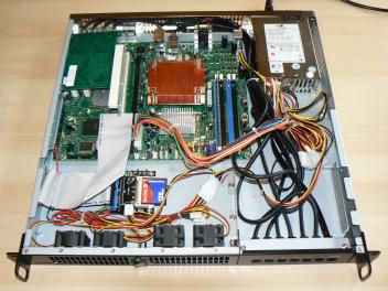 |
| Figure 26: Spacer and rubber foot beneath the IDE-to-CF adapter. | Figure 27: The chassis with everything wired and mounted. |
|---|
Repeat for the second machine, and you've got yourself a pair of firewalls ready for OpenBSD! While these instructions are pretty specific to the hardware I used, I'm not trying to suggest that my configuration is exactly what you should use. In fact, if I had to do it all over again, I'd change a few things: the PCI card situation is hackish, and a proper CPU fan duct would be nice. Rather, I'm hoping that by detailing my experience, you can get a feel for the things to consider when ordering parts and a general understanding of what's involved in building a dedicated 1U firewall.
Stay tuned for part 2 which will address getting OpenBSD running on these firewalls and configuring PF and CARP for redundant operation.
If you find any glaring errors or just want to comment, please let me know!